
Introduction
Metal-Organic Frameworks (MOFs) are a class of crystalline materials comprising both inorganic and organic constituents arranged in an extended network. Unlike Covalent Organic Frameworks (COFs), MOFs are typically composed of metal ions or clusters (referred to as nodes) connected by organic ligands (linkers). The design of MOFs relies heavily on the appropriate selection of building blocks, particularly rigid organic linkers, which determine both the topology and the functional properties of the resulting framework.
Organic ligands used in MOFs often incorporate aromatic moieties that provide the necessary rigidity and spatial orientation to form one-, two-, or three-dimensional porous networks. These aromatic linkers are typically terminated with functional groups—such as carboxylates, pyridyls, phosphonates, or sulfonates—that enable coordination with metal ions. Common metal centers include Zn²⁺, Fe³⁺, Mg²⁺, Ca²⁺, Zr⁴⁺, Ni²⁺, Co²⁺, Cu²⁺, and Al³⁺. MOFs are renowned for their large specific surface areas, high porosity, thermal stability, and the ability to tailor their pore environments for targeted applications.
The tunability of MOFs via the selection of linkers and metal centers allows for precise control over properties such as pore size, surface chemistry, and adsorption capacity. These attributes make MOFs suitable for various fields, including gas storage and separation, heterogeneous catalysis, and biomedical delivery systems.
2. Synthesis of Metal-Organic Frameworks (MOFs)
The development of novel MOF materials is influenced by multiple parameters including the choice of metal ions, the type of organic linkers, reaction conditions, and crystallization methods. The structural diversity of MOFs can be attributed to systematic exploration of these parameters through various synthesis techniques. The principal synthesis strategies are described below:
2.1 Hydrothermal and Solvothermal Methods
Hydrothermal and solvothermal synthesis are among the most common methods for producing MOFs. These processes involve the reaction of metal salts and organic ligands in high-boiling solvents—such as DMF (dimethylformamide), DMA (dimethylacetamide), or DEF (diethylformamide)—under elevated temperature and pressure, typically in sealed autoclaves.
Reaction parameters including solvent composition, metal-to-ligand ratio, temperature, and the use of modulators (e.g., acetic acid, benzoic acid, or HCl) can influence the crystal morphology, size, and defect structures of the MOFs. Modulators play a critical role by temporarily coordinating with metal centers to slow down the nucleation process and promote the formation of well-defined crystals.
Despite its ability to produce high-quality MOF crystals suitable for single-crystal X-ray diffraction, solvothermal synthesis is often time-consuming, with reaction times ranging from several hours to days.
2.2 Microwave-Assisted Synthesis
Microwave (MW)-assisted synthesis offers a rapid alternative to conventional heating methods. By directly interacting with polar solvents and reactants, microwave energy induces localized heating (hot spots), thereby accelerating nucleation and crystal growth. MOFs such as MOF-5, HKUST-1, and IRMOFs have been synthesized in minutes using this method.
MW-assisted synthesis typically results in smaller particle sizes and shorter reaction times compared to solvothermal routes. However, it often produces crystals that are too small for detailed structural analysis using single-crystal XRD.
2.3 Sonochemical Synthesis
Sonochemical methods use high-frequency ultrasonic waves (20 kHz to 10 MHz) to induce acoustic cavitation—formation, growth, and implosive collapse of microbubbles in the solvent. This results in localized high pressures (>1000 atm) and temperatures (>5000 K), promoting rapid reaction kinetics.
MOFs such as MOF-177, Mg-MOF-74, and MIL-53(Fe) have been successfully synthesized via this route. The key advantage lies in reduced synthesis time and temperature. However, the method often yields nanocrystalline materials unsuitable for structural characterization.
2.4 Electrochemical Synthesis
Electrochemical synthesis involves the in situ generation of metal ions at the anode in an electrochemical cell containing the organic ligand at the cathode. This method is advantageous due to high product purity and the absence of counterions such as nitrates or chlorides.
HKUST-1 (Cu-MOF) and other copper-based MOFs have been synthesized using this method. Additionally, large-scale production of MOFs like Al-fum (Basolite A520) has been achieved using water-based electrochemical processes. While highly scalable and clean, this method requires precise control of current, voltage, and electrolyte composition.
2.5 Mechanochemical Synthesis
Mechanochemical or solvent-free synthesis is an environmentally friendly approach involving the application of mechanical force (e.g., grinding or milling) to induce chemical reactions. Mortar and pestle or ball mills are commonly used to mix metal precursors and ligands.
Mechanochemical synthesis eliminates the need for large solvent volumes and facilitates the use of low-solubility metal salts (e.g., oxides, carbonates). However, this method often produces poorly crystalline materials and is limited in scalability.
Mechanochemical approaches include:
- Solvent-Free Grinding (SFG)
- Liquid-Assisted Grinding (LAG)
- Ion and Liquid-Assisted Grinding (ILAG)
2.6 Slow Diffusion Technique
The slow diffusion method involves layering solutions of metal salts and ligands separated by an inert solvent layer. Over time, diffusion of reactants leads to controlled crystallization at the interface. This technique can yield high-quality single crystals suitable for structural analysis.
2.7 Solvent Evaporation and Ionothermal MethodsThese methods rely on slow concentration of the reaction mixture through solvent evaporation or the use of ionic liquids (ionothermal synthesis). These routes offer additional control over crystal size and morphology and have been used to synthesize copper- and lanthanide-based MOFs.
2.8 Other Emerging Methods
Additional methods used in MOF synthesis include:
- Template-assisted synthesis
- Atomic layer deposition (ALD)
- Spray drying
- Sol–gel synthesis
- Supercritical fluid synthesis
- Flow chemistry
Each of these offers unique advantages in terms of scalability, crystal morphology, or environmental compatibility.
Table 1. Summary of Common MOF Synthesis Methods
| Synthesis Method | Key Features | Advantages | Limitations |
|---|---|---|---|
| Solvothermal/Hydrothermal | Uses high-temp, high-pressure solvents | Produces high-quality crystals | Time-consuming, requires autoclaves |
| Microwave-Assisted | Uses microwave radiation for heating | Rapid synthesis, smaller particles | Poor crystal quality for XRD |
| Sonochemical | Uses ultrasonic waves | Fast reaction, ambient conditions | Yields nano-sized, poorly crystalline MOFs |
| Electrochemical | In situ generation of metal ions | High purity, scalable | Needs precise control and equipment |
| Mechanochemical | Solvent-free grinding | Green chemistry, no solvent waste | Poor scalability, low crystal quality |
| Slow Diffusion | Gradual mixing via diffusion layers | High-quality crystals | Limited to small-scale synthesis |
| Solvent Evaporation | Crystallization via evaporation | Simple setup | Long reaction time |
| Ionothermal | Uses ionic liquids | Stable frameworks, novel structures | Cost of ionic liquids |
3. Activation of Metal-Organic Frameworks (MOFs)
MOFs are typically categorized as either rigid or flexible frameworks. Rigid MOFs maintain their structural integrity under varying environmental conditions and possess permanent porosity similar to zeolites. In contrast, flexible MOFs exhibit dynamic structural responses—such as framework expansion or contraction—when exposed to changes in temperature, pressure, or the presence of guest molecules.
One of the most crucial post-synthetic steps is activation, a process aimed at removing trapped guest molecules such as solvents, unreacted ligands, or modulators from the pores of the MOF. This step is essential to fully access the intrinsic porosity and surface area of the material. Inadequate or harsh activation conditions can lead to framework collapse, loss of crystallinity, or incomplete removal of guest species.
Various activation strategies have been developed to preserve the structural integrity of MOFs while maximizing their surface area and porosity.
However, in many cases, heating alone may induce pore collapse due to high surface tension forces during solvent evaporation. Therefore, while thermal activation is simple and efficient for stable MOFs, it may not be suitable for more delicate structures.
3.2 Solvent-Exchange Activation
To mitigate the risks of framework degradation during thermal activation, solvent-exchange strategies are employed. High-boiling-point solvents like DMF are replaced with lower-boiling-point alternatives such as chloroform, acetone, or ethanol. These solvents have lower surface tension, reducing capillary forces during evaporation.
Yaghi et al. pioneered this technique during the activation of MOF-5, where chloroform replaced DMF. The surface area increased significantly upon activation. Similarly, IRMOF-3 and IRMOF-16 displayed enhanced porosity after replacing DMF with chloroform or THF.
Example SBET values post solvent-exchange:
- IRMOF-3: from 10 m²/g → 1800 m²/g
- IRMOF-16: from 0 m²/g → 470 m²/g
Despite these improvements, solvent exchange may not always achieve the theoretical porosity due to incomplete guest removal or framework rigidity.
3.3 Supercritical CO₂ (ScCO₂) Activation
Supercritical carbon dioxide (ScCO₂) activation circumvents the liquid–gas phase transition entirely by using CO₂ in its supercritical state. This method avoids surface tension effects and prevents pore collapse. It is especially useful for fragile MOFs that are not tolerant to traditional heating or solvent exchange.
Notable advantages:
- Avoids capillary stress.
- Scalable and cost-effective.
- Environmentally benign.
Table 2. MOFs Activated with ScCO₂ and Their Performance
| MOF | SBET (m²/g) | Pore Volume (cm³/g) | Reference |
|---|---|---|---|
| NU-110 | 7140 | 4.40 | [113] |
| MOF-210 | 6240 | 3.60 | [118] |
| SNU-70′ | 5290 | 2.17 | [119] |
| [Co₆(btb)₄(bp)₃] | 5200 | 2.10 | [120] |
| UMCM-9 | 4970 | 1.80 | [121] |
| Bio-MOF-100 | 4300 | 4.30 | [122] |
| FJI-1 | 4043 | 1.43 | [123] |
| DUT-13 | 2532 | 1.98 | [124] |
In addition, “flowing ScCO₂ activation” involves passing ScCO₂ through a column packed with MOF material, effectively removing solvent without requiring liquid-phase replacement. This technique minimizes material damage and is suitable for industrial scale-up.
3.4 Freeze-Drying (Lyophilization)
Freeze-drying involves the exchange of guest solvents with low-boiling-point organic solvents (e.g., benzene or cyclohexane), followed by freezing and sublimation under vacuum. This process bypasses the liquid state, thereby reducing surface tension effects.
Lin et al. demonstrated this method by activating Cu-paddlewheel-based MOFs using benzene. The freeze-dried materials displayed higher surface areas and better crystallinity than those activated via conventional methods.
To avoid toxicity concerns with benzene, alternative solvents such as cyclohexane have been used effectively.
3.5 Chemical Activation
Some MOFs incorporate ionic or strongly coordinating species—such as benzoic acid or DMF—during synthesis, which are not readily removable by vacuum or solvent exchange. In such cases, chemical treatment with acids (e.g., HCl) or coordination-displacing agents is necessary.
Examples:
- PCN-222 (MOF-545): Treated with HCl to remove benzoate modulators, increasing pore volume.
- NU-1000: Acid treatment cleaved benzoate ligands from Zr₆ nodes, producing a more open framework.
Multiple coordination exchange (CE) steps using a sequence of solvents (e.g., MeCN → MeOH → EtOH → DCM) have also been used to activate open metal sites in MOFs such as MOF-74 (Ni).
Table 3. Comparison of Activation Strategies
| Activation Method | Principle | Suitable For | Limitations |
|---|---|---|---|
| Thermal + Vacuum | Heat to desorb solvent | Thermally stable MOFs | May cause pore collapse |
| Solvent Exchange | Replace with low-boiling solvent | Fragile MOFs | Partial porosity loss possible |
| Supercritical CO₂ | Bypass liquid-gas transition | Sensitive or large MOFs | Requires special equipment |
| Freeze-Drying | Solvent replacement + sublimation | MOFs with low volatility | Toxic solvents, multi-step process |
| Chemical Activation | Acid or coordination displacement | MOFs with strong modulators | Risk of framework degradation |
4. Characterization of Metal-Organic Frameworks (MOFs)
Thorough characterization of MOFs is essential for confirming their structure, purity, thermal stability, porosity, and suitability for specific applications. A wide range of analytical techniques are used to evaluate the physicochemical properties of MOFs, each offering distinct but complementary information.
4.1 Single-Crystal X-ray Diffraction (SCXRD)
SCXRD is the most definitive technique for elucidating the precise three-dimensional structure of MOFs. It provides information on the arrangement of metal nodes and organic linkers, pore sizes, interpenetration, and framework symmetry.
However, SCXRD requires large, high-quality single crystals (>50 µm), which can be difficult to obtain. Furthermore, MOF crystals often contain disordered solvent molecules, making structural refinement challenging. The SQUEEZE algorithm is commonly used to remove diffuse electron density from solvent-filled voids during data processing.
Despite these challenges, SCXRD remains invaluable for structural determination and serves as a reference for comparing experimental and simulated data.
4.2 Powder X-ray Diffraction (PXRD)
PXRD is used when crystals are too small for SCXRD. It assesses the crystallinity and phase purity of bulk MOF samples. Sharp peaks in the diffraction pattern indicate a well-ordered structure, while peak broadening may result from small crystal size or poor ordering.
Experimental PXRD patterns are compared to simulated patterns derived from SCXRD data to confirm product identity. Techniques such as capillary rotation during data collection minimize preferred orientation effects.
4.3 Elemental Analysis (CHN)
Elemental analysis measures the percentage composition of carbon, hydrogen, and nitrogen in MOFs, and compares it to theoretical values calculated from the proposed formula. This technique is useful for verifying chemical composition and detecting residual solvents or impurities.
4.4 Thermogravimetric Analysis (TGA)
TGA monitors weight loss of MOFs as a function of temperature. It reveals the thermal stability and decomposition profile of the framework, and helps estimate guest solvent content.
Typical TGA profiles show multiple steps:
- Initial weight loss: loss of solvent or water
- Intermediate loss: decomposition of organic linkers
- Residual weight: metal oxides or carbonates
TGA data may be complemented by in situ PXRD or variable-temperature gas sorption to assess structural integrity upon heating.
4.5 Surface Area and Porosity Measurements
MOFs are renowned for their high surface areas and porosity. These are commonly assessed via nitrogen adsorption-desorption isotherms at 77 K. Prior to measurement, MOFs must be properly activated to remove guest molecules.
Key Metrics:
- BET surface area (SBET): Calculated using the Brunauer-Emmett-Teller (BET) equation.
- Langmuir surface area: Generally overestimates surface area compared to BET.
- Pore volume and pore size distribution: Estimated using DFT (Density Functional Theory) or BJH (Barrett–Joyner–Halenda) methods.
Rule of Thumb: Sample mass × SBET should be ≥100 m² to ensure reliable results.
BET Equation:
PV(P0−P)=1VmC+C−1VmC⋅PP0\frac{P}{V(P_0 – P)} = \frac{1}{V_m C} + \frac{C – 1}{V_m C} \cdot \frac{P}{P_0}V(P0−P)P=VmC1+VmCC−1⋅P0P
Where:
- PPP = equilibrium pressure
- P0P_0P0 = saturation pressure
- VVV = volume adsorbed
- VmV_mVm = monolayer capacity
- CCC = BET constant
Rouquerol Criteria are applied to select a linear region of the BET plot for accurate surface area calculation.
4.6 Infrared Spectroscopy (FT-IR)
Fourier-transform infrared (FT-IR) spectroscopy is used to detect the functional groups present in MOFs. It confirms ligand-metal coordination (e.g., carboxylate shifts), and helps identify uncoordinated ligands or guest molecules.
4.7 Scanning Electron Microscopy (SEM) and Energy-Dispersive X-ray Spectroscopy (EDX)
SEM provides high-resolution images to assess crystal morphology, size, and uniformity. When coupled with EDX, it also gives semi-quantitative elemental composition and distribution data.
4.8 Inductively Coupled Plasma Optical Emission Spectroscopy (ICP-OES)
ICP-OES is used to precisely quantify the metal content of MOFs. It is especially useful when elemental ratios or residual metal content from precursors need verification.
4.9 Nuclear Magnetic Resonance (NMR) Spectroscopy
Although most MOFs are insoluble, solution-state NMR can be used after digestion with acids (e.g., D₂SO₄ or HF) to verify linker identity, ligand-metal ratios, and the presence of modulators or solvent residues.
In contrast, solid-state NMR (SS-NMR) offers non-destructive characterization of local environments and coordination states of atoms such as ^13C, ^31P, and ^15N. It is valuable for studying functional groups, oxidation states, and dynamics within the MOF framework.
4.10 Gas Adsorption Measurements
Gas sorption studies (e.g., CO₂, CH₄, H₂) are critical for evaluating MOFs in storage or separation applications. Adsorption capacity at varying pressures and temperatures correlates with pore volume and surface area.
Two measurement techniques are common:
- Gravimetric: Measures mass changes.
- Volumetric: Measures pressure changes.
Gravimetric methods require high-purity gases, while volumetric methods are more user-friendly but susceptible to cumulative errors.
Table 4. Common MOF Characterization Techniques and Their Purpose
| Technique | Purpose | Remarks |
|---|---|---|
| SCXRD | Precise atomic structure | Requires large, high-quality crystals |
| PXRD | Crystallinity and phase purity | Useful for bulk materials |
| Elemental Analysis | CHN content validation | Indicates purity and solvent presence |
| TGA | Thermal stability and solvent content | Often coupled with PXRD |
| N₂ Adsorption (BET) | Surface area and porosity | Requires proper activation |
| FT-IR | Functional group identification | Tracks coordination shifts |
| SEM/EDX | Morphology and elemental mapping | Visual and semi-quantitative |
| ICP-OES | Metal quantification | Highly precise, useful for composition check |
| NMR (solution/solid) | Ligand analysis and metal-linker ratios | Requires digestion or advanced SS-NMR setup |
| Gas Sorption | Gas uptake and selectivity | Key for CO₂, H₂, CH₄ storage |
5. Organic Linkers in MOFs
Organic linkers play a pivotal role in dictating the structure, topology, porosity, and functionality of MOFs. These ligands coordinate with metal nodes (secondary building units or SBUs) to form extended frameworks. The length, rigidity, connectivity (e.g., ditopic, tritopic, tetratopic), and functional groups of the linkers profoundly influence the final properties of the MOF.
Categories of Organic Linkers:
- Carboxylates (e.g., BDC, BTC)
- Nitrogen-containing heterocycles (e.g., pyridine, bipyridine)
- Phosphonates and sulfonates
- Hybrid and multifunctional ligands
5.1 Ditopic Carboxylate Linkers
Ditopic linkers contain two coordination sites and are widely used due to their ability to form linear or square-planar coordination geometries with metals. A classic example is MOF-5, constructed using benzene-1,4-dicarboxylate (BDC) and Zn²⁺ ions.
Examples of structures:
- MOF-118: Cu paddle-wheel clusters + 4,4′-biphenyldicarboxylate (BPDC)
- MOF-601: Cu clusters + 2,2′-dicyano-4,4′-biphenyldicarboxylate
- Zn(BDC)(DMF)(H₂O): Formed under ambient conditions using BDC
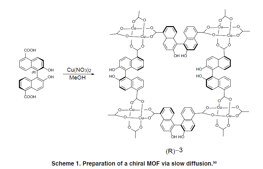
Scheme 1 illustrates the slow-diffusion synthesis of a chiral MOF using a binaphthyl-based ditopic linker.
5.2 Tritopic Carboxylate Linkers
These linkers coordinate at three points, enabling the construction of triangular or trigonal frameworks.
Notable MOFs:
- MOF-177: Zn₄O clusters + benzene-1,3,5-tricarboxylate (BTC); SBET ≈ 4500 m²/g
- MIL-100(Cr): Cr₃O cluster + BTC; two mesoporous cages (25 Å, 29 Å)
- HKUST-1 (MOF-199): Cu paddle-wheel + BTC; SBET ≈ 692 m²/g
Advanced linkers:
- TATAB and TATB: Triazine-based, used in meso-MOFs and PCN-6
- BBC and BTE: Extended tritopic linkers used to construct highly porous MOFs such as MOF-180 and MOF-200
5.3 Tetratopic Carboxylate Linkers
Tetratopic linkers offer four coordination points, often with tetrahedral geometry (Td symmetry), which allows the construction of three-dimensional, highly porous frameworks.
Key Examples:
- MOF-11: Constructed with 1,3,5,7-adamantane tetracarboxylate (ATC)
- PCN-521: Built from 4,4′,4″,4‴-methanetetrayltetrabenzoate (MTBC) and Zr₆ clusters; SBET ≈ 3411 m²/g
- IMP series: Prepared using silicon-centered linkers like TCPS (tetrakis-carboxyphenylsilane), yielding MOFs such as IMP-8, IMP-9, IMP-10, etc.
PCN-512 and PCN-511:
- Prepared from TCPS and copper/zinc nodes
- Exhibit high solvent accessibility and surface area
- PCN-511 (freeze-dried): SBET ≈ 1284 m²/g
Other linkers like TCPPDA (semi-rigid) and BDIP/ADIP enable the formation of MOFs with pts topology and exceptional gas adsorption performance.
5.4 Hexatopic and Octatopic Linkers
Multitopic linkers allow the construction of ultra-high-connectivity frameworks and open up possibilities for new topologies.
Examples:
- PCN-61 to PCN-610: Built using BTEI and NTEI hexatopic linkers
- NU-110: Constructed using extended hexatopic linkers with ethyne bridges; reported SBET ≈ 7140 m²/g
- UHM series (e.g., UHM-6): Silicon-based linkers used with copper paddle-wheels; show high porosity and CO₂ uptake
Table 5. Representative Linkers and Associated MOFs
| Linker Type | Example Ligands | Associated MOFs | Notable Features |
|---|---|---|---|
| Ditopic | BDC, BPDC, CNBPDC | MOF-5, MOF-601, MOF-118 | Linear geometry, 1D/2D frameworks |
| Tritopic | BTC, TATB, BBC, BTE | MOF-177, HKUST-1, PCN-6 | Trigonal topology, mesoporosity |
| Tetratopic | MTBC, TCPS, TCPPDA | PCN-521, IMP-10, MOF-11 | 3D networks, large voids |
| Hexatopic | BTEI, NTEI, BTTB | NU-110, PCN-66 | High porosity, large pore volumes |
| Octatopic | BTTTC, TEHPA | Under research | Potential for novel topologies |
5.5 Functional and Heteroatom-Containing Linkers
To impart specific chemical functionality, MOFs have also been constructed using:
- Nitrogen-based heterocycles: e.g., bipyridines, triazoles
- Phosphonate/sulfonate groups: Promote stronger coordination, often with higher thermal stability
- Silicon- and boron-containing cores: Underexplored but offer unique geometry and thermal resistance
These advanced linkers offer greater flexibility in framework design, hydrophilicity/hydrophobicity control, and active site incorporation.
6. Applications of Metal-Organic Frameworks (MOFs)
Metal-Organic Frameworks have garnered significant research attention due to their structural versatility, tunable porosity, and exceptionally high surface areas—often exceeding 5000 m²/g. These features, combined with their chemical and thermal stability, have opened diverse application areas for MOFs in both academic and industrial settings.
6.1 Gas Storage and Separation
MOFs are excellent candidates for gas storage, particularly hydrogen (H₂), methane (CH₄), and carbon dioxide (CO₂). Their pore volumes (up to 90%) and tunable pore chemistries allow for the selective adsorption and separation of gas molecules. At high pressures, gas uptake is largely dependent on the void volume, while at low pressures, the uptake correlates with adsorption enthalpy and functional groups present in the framework.
Applications:
- Hydrogen Storage: High gravimetric and volumetric storage capacities under cryogenic conditions.
- Methane Storage: For natural gas vehicles (NGVs) due to high-pressure methane uptake.
- Carbon Capture and Storage (CCS): Effective adsorption of CO₂ from flue gas or ambient air.
Example: MOFs such as MOF-177 and MIL-101(Cr) exhibit SBET values of 4500 and 4100 m²/g respectively, making them efficient for CO₂ and H₂ capture.
6.2 Catalysis
Due to the presence of metal nodes and tunable organic linkers, MOFs serve as efficient heterogeneous catalysts. They can act as:
- Lewis acid/base catalysts
- Photocatalysts
- Oxidation or hydrogenation catalysts
Their large surface areas provide ample active sites, and post-synthetic modification allows for incorporation of specific functional groups or metal nanoparticles.
Example: Cu-MOFs and Zr-based MOFs have been extensively used in oxidation reactions and biomass conversion due to their redox-active centers.
6.3 Drug Delivery and Biomedical Applications
The biocompatibility, biodegradability, and tunable pore sizes of certain MOFs allow for controlled drug loading and release. pH-sensitive or stimuli-responsive MOFs can selectively release drugs in targeted environments, such as acidic tumor tissues.
Features:
- High drug encapsulation efficiency
- Targeted and sustained release
- Biocompatible scaffolds (e.g., ZIF-8, MIL-101(Fe))
Example: MIL-101(Fe) has been used for the controlled delivery of ibuprofen, while ZIF-8 is explored for anticancer drug delivery due to its pH-sensitive degradation in acidic environments.
6.4 Gas Sensing and Chemical Sensors
The interaction of MOFs with analyte molecules can induce measurable changes in electrical, optical, or mass properties. Their high surface area and functional groups make them sensitive and selective sensors.
Applications:
- Detection of volatile organic compounds (VOCs)
- Toxic gas sensing (e.g., NO₂, NH₃)
- Humidity sensors
6.5 Water Harvesting and Desalination
Some MOFs possess high water adsorption capacity at low relative humidity, making them suitable for atmospheric water harvesting (AWH). Their adsorption-desorption cycling stability enhances their utility in harsh environments.
Example: MOF-303 and MOF-801 have demonstrated excellent water uptake capacity and cycling performance in desert conditions.
6.6 Energy Storage and Conversion
MOFs are emerging as electrode materials for batteries, supercapacitors, and electrocatalysts due to their redox-active sites and high conductivity when modified with conductive polymers or carbon-based materials.
Applications:
- Lithium-ion batteries (Li-ion)
- Supercapacitors
- Electrocatalysts for oxygen evolution/reduction
6.7 Environmental Remediation
MOFs can remove toxic metals, organic dyes, and radioactive elements from aqueous solutions due to their high affinity, large pore volumes, and customizable surface chemistry.
Example:
- Removal of heavy metals like Pb²⁺, Cr⁶⁺
- Adsorption of organic pollutants such as methylene blue, rhodamine B
Table 6. Key Application Areas of MOFs
| Application Area | Description | Example MOFs | Notable Attributes |
|---|---|---|---|
| Gas Storage | H₂, CH₄, CO₂ storage and CCS | MOF-177, MIL-101 | High surface area, tunable porosity |
| Catalysis | Oxidation, hydrogenation, photocatalysis | Cu-MOFs, Zr-MOFs | Metal nodes as active centers |
| Drug Delivery | Targeted, pH-sensitive release | ZIF-8, MIL-101(Fe) | Biocompatible, high drug loading |
| Sensors | VOC and gas detection | Zn-MOFs, ZIFs | High sensitivity and selectivity |
| Water Harvesting | AWH and desiccant materials | MOF-801, MOF-303 | High water uptake at low RH |
| Energy Storage | Batteries and capacitors | MOF-derived carbons | Redox-active and conductive frameworks |
| Environmental Cleanup | Adsorption of metals/dyes/pollutants | UiO-66, MIL-53(Fe) | High affinity, functionalized surfaces |
7. Conclusion
Metal-Organic Frameworks (MOFs) represent a frontier in material science due to their modular architecture, exceptionally high surface areas, and tunable porosity. Their design is driven by the judicious selection of metal centers and organic linkers, allowing for the creation of structurally diverse and functionally rich frameworks. The versatility of MOFs has made them promising materials in applications ranging from gas storage, catalysis, and sensing, to drug delivery and environmental remediation.
In this review, we have presented a comprehensive summary of MOF synthesis strategies, including traditional methods such as solvothermal and electrochemical synthesis, and emerging techniques like mechanochemistry and supercritical CO₂ activation. We also discussed the importance of activation methods in achieving optimal porosity and the key characterization tools required to understand MOF structures and properties.
Particular emphasis was placed on the role of organic linkers—carboxylates, nitrogen-based heterocycles, and multitopic architectures—which determine the framework’s dimensionality, pore geometry, and functional capabilities. Although MOF research has made tremendous strides, there remains a notable gap in the exploration of silicon- and boron-containing linkers, which could offer new structural motifs and functional advantages.
This review aims to serve as a foundation for researchers, industrial scientists, and students seeking to design and apply MOFs in both academic and real-world settings. Future advancements in computational design, green synthesis, and scalable manufacturing will likely propel MOFs from laboratory curiosities to industrial mainstays.
Acknowledgment
The authors gratefully acknowledge the support of the Department of Chemistry, and the Department of Medical Laboratory Science for providing the necessary resources and facilities used in the development of this review article.
References
- Férey, G., et al. Science, 2005, 309, 2040–2042.
- Yaghi, O.M., et al. Nature, 2003, 423, 705–714.
- Rowsell, J.L.C., Yaghi, O.M. Micropor. Mesopor. Mater., 2004, 73, 3–14.
- Côté, A.P., et al. Science, 2005, 310, 1166–1170.
- Chui, S.S.Y., et al. Science, 1999, 283, 1148–1150.
- Li, H., et al. Nature, 1999, 402, 276–279.
- Furukawa, H., Cordova, K.E., O’Keeffe, M., Yaghi, O.M. Science, 2013, 341, 1230444.
- Kitagawa, S., Kitaura, R., Noro, S. Angew. Chem. Int. Ed., 2004, 43, 2334–2375.
- Férey, G. Chem. Soc. Rev., 2008, 37, 191–214.
- Horcajada, P., et al. Nat. Mater., 2010, 9, 172–178.
- Férey, G., Serre, C. Chem. Soc. Rev., 2009, 38, 1380–1399.
- Murray, L.J., Dincă, M., Long, J.R. Chem. Soc. Rev., 2009, 38, 1294–1314.
- Yang, D.A., et al. Micropor. Mesopor. Mater., 2012, 157, 137–145.
- Zhou, H.C., Long, J.R., Yaghi, O.M. Chem. Rev., 2012, 112, 673–674.
- Wang, C., et al. Chem. Soc. Rev., 2016, 45, 5107–5134.
- Kreno, L.E., et al. Chem. Rev., 2012, 112, 1105–1125.
- Tanabe, K.K., Cohen, S.M. Chem. Soc. Rev., 2011, 40, 498–519.
- Liu, J., et al. Chem. Soc. Rev., 2014, 43, 6011–6061.
- Ma, L., Abney, C., Lin, W. Chem. Soc. Rev., 2009, 38, 1248–1256.
- Burtch, N.C., Jasuja, H., Walton, K.S. Chem. Rev., 2014, 114, 10575–10612.